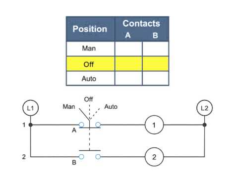
Hand Off Auto Switch Contacts
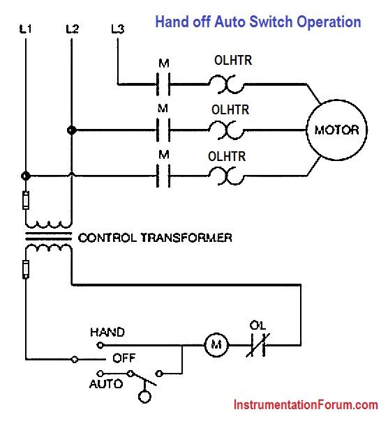
Hand Off Auto Switch Operation Electrical Engineering Instrumentation Forum

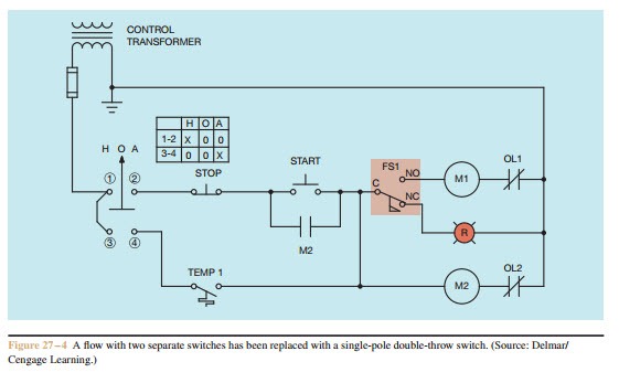
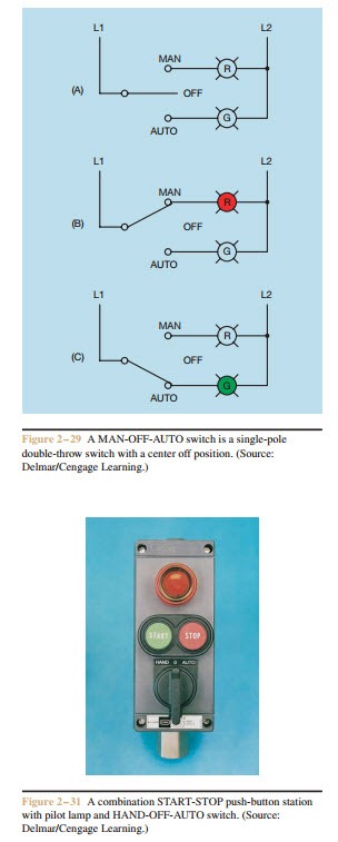
Hand Off Automatic Controls Basic Control Circuits
Selector Switches And Contacts In A Diagram What They Do Youtube

Hand Off Auto Circuits Full Lecture Youtube

Hand Off Automatic Controls
Hand Off Automatic Controls Electric Equipment

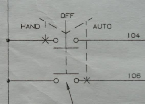
Draw and label the nema sybols for both a two position off on selector switch and a three position hand off auto selector switch.
Hand off auto switch contacts.
Understanding Hoas To Avoid Confusion For Plant Personnel Scadaware
Symbols Electric Motors Generators Engineering Eng Tips

Industrial Motor Control Symbols And Schematic Diagrams
Selector Switches Diagram Video And Selector Switch Product Oveview
Functions Of Motor Control Selector Switches Electric Equipment

Motor Control Devices Part 1
Eaton 10250t22kb Pop Assembled Selector Switches Pilot Devices Control Automation Platt Electric Supply

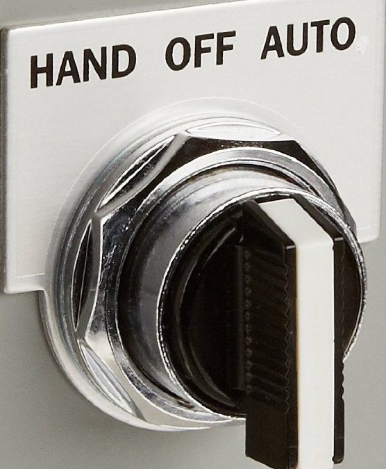
Hoa Switch How It Work Youtube

How To Draw A 2 Position Selector Switch And Its Contacts Iec World Circuit Design Eng Tips

Practical Machinist Largest Manufacturing Technology Forum On The Web
Wiring Push Buttons And Selector Switch To Click Plc Acc Automation

Square D 8903 Lighting Contactor Wiring Diagram Lighting Style From Square D 8903 Lighting Contactor Wiring Diagram Pictures

Tt 0686 Phase Motor Starter Wiring Diagram 3 Phase Motor Starter Wiring Download Diagram

Schneider Electric 30 Mm 3 Position Selector Switch Assembly 9001as2 The Home Depot
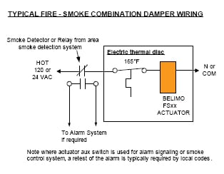
The 1 Asked Question About Fire And Smoke Dampers

Industrial Switch Types Toggle Push Button Selector Switch Etc

New Wiring Gfci To Switch Diagram Diagram Diagramsample Diagramtemplate Wiringdiagram Diagramchart Worksheet Worksheettemplat Diagram Diagram Chart Gfci
How To Make A Remote On And Off Switch With A Contactor Latching Circuit Youtube
Https Encrypted Tbn0 Gstatic Com Images Q Tbn 3aand9gcrzxarxzemhjc0ges1awcjyy4ewhggbkezeqjq3cntnfpsnxyde Usqp Cau

Chapter 6 Electromagnetic Control Relays 6 1 A Plc Was Designed To Replace Control Relays That Made Logic Decisions An Electrical Relay Is A Magnetic Ppt Download

New Honeywell Thermostat Rth2310 Wiring Diagram Diagram Diagramsample Diagramtemplate Wiringdia Light Switch Wiring Thermostat Wiring Honeywell Thermostats
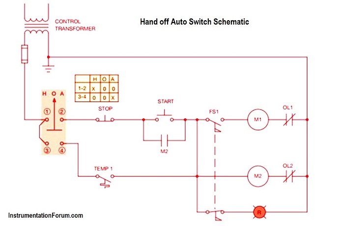
Diagram Farmall 460 Wiring Diagram Full Version Hd Quality Wiring Diagram Voipdiagrams Unicefflaubert Fr

When Heavy Motor Systems Or High Current Motors Are Involved Initial Switch On Current Surge Electronic Circuit Projects Circuit Projects Electronics Circuit

17 Dual Electric Fan Wiring Diagram With Relaydual Electric Fan Wiring Diagram With Relay Wiring Diagr In 2020 Electric Radiator Fan Radiator Fan Electric Cooling Fan
Source : pinterest.com
